KLAGENFURT – CARINTHIA
Simulation Transferability

1 Mathematical Definitions
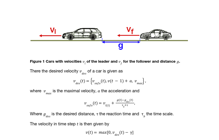
With Eclipse SUMO a simulation environment was chosen for the microscopic traffic flow simulation, which is already equipped with a large number of implemented vehicle following models. In addition to the standard Krauss model (Krauss et al., 1997 [1]), which was assigned to conventional vehicles, a variant of the ACC and CACC following behaviour is already implemented and parameterizable. In parallel, special lane change behaviours are implemented, which also have their own parameters. The two vehicle following models are based on the work of Milanés and Shladover (2014)[2] and Milakis et al. (2017) [3], who implemented the control mechanism for the speed control, distance control, and distance change control modes in the TransAID project (Porfyri et al., 2018)[4]. For better integration into the SUMO ecosystem, the collision avoidance mode was also integrated, as the original control loop led to problems when used in platoon mode (multiple individual vehicles join together to form a vehicle formation with overall control of speed, distance, and lane change behaviour by a lead vehicle) for lateral distance selection.
For the Lane changing and the Intersection model, standard SUMO Models were applied. The description of the models can be found in the Monheim and Linköping documents.
There, an intelligent driver model was used to model car fllowing behaviour. Here we use the model described in Krauss et al., 1997 [1].

The parametera changed for the implementation in Klagenfurt are given in the following.
In principle, the vehicle following models in SUMO have their own parameter sets, but some are shared by all models:
- actionStepLength: A representation of the reaction time in SUMO, which is a measure of the calculation steps per simulation second. By default, a value of 1.0 is preset, which corresponds to one calculation step per simulation second.
- tau: The distance desired by the driver between their own vehicle and the bumper of the lead vehicle.
- Acceleration behaviour (decel, apparentDecel, emergencyDecel): Specification of desired acceleration values that represent limits for acceleration distributions in microsimulation.
In the area of automated driving functions, the implementations of the ACC and CACC driving functions are used for the longitudinal controls of the vehicles. Lateral control is represented by the lane change models, which provide similar access to the DLL solution in PTV Vissim. The following modes are implemented in ACC and CACC:
- Speed control Mode
- Serves to maintain the predefined desired speed and is activated as soon as no lead vehicle is detected within 120 meters.
- Gap control mode
- Used to control a constant time gap between vehicles and is activated as soon as the time gap is less than 0.2 meters, and the speed difference is less than 0.1 meters/second.
- Gap-closing control mode
- Defines the link between speed control mode and gap control mode and is triggered by a distance of less than 100 meters to the lead vehicle. Between 100 and 120 meters distance the previous control strategy is maintained, outside these values the distance is adjusted by speed changes.
- Collision avoidance control mode
- Was introduced as an additional control loop in the distance behaviour because underruns of the control loops were detected in test simulations in the TransAID project, resulting in clusters of collisions. This control loop controls the behaviour in safety-critical situations, such as low time-to-collision (TTC) values, by adapting the desired speeds and desired acceleration or braking behaviour.
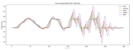
The figure below shows the sequence of a platooning simulation carried out in the course of the TransAID project, in which five vehicles were combined into a vehicle convoy using ACC and CACC following behaviour and performed different driving manoeuvres, such as changing lanes or entering a highway. It shows the differently parameterized control approaches of the speed in relation to the lead vehicle (“first”).

Figure 39: Following behaviour of ACC vehicles (Eclipse SUMO – ACC following model)
Another central function of each microsimulation environment is also the lane change behaviour of the simulated individual vehicles, in which basic functions such as limits for the lane change decision and accepted time gaps between vehicles on the target lane, as well as the longitudinal distance behaviour to the vehicle on the current lane before and during the lane change process (e.g., whether short-term underruns of the limit time gaps to the lead vehicle) are defined short-term underruns are allowed.
Three lane change models are implemented in Eclipse SUMO, LC2013 (default model in Eclipse SUMO), SL2015 and DK2008. While DK2008 is the oldest model and has been replaced by the LC2013 model, the SL2015 model has been implemented for improved representation of sub-lane behaviour. Eclipse SUMO supports simulation of non-lane traffic by using a finer resolution lane model, the sub-lane model, but this is not used in Symul8. Using the LC2013 lane change model, allows implementing strategic and cooperative lane changes as well as tactical lane changes to achieve optimized travel time. By means of suitable parameters in vehicle type definitions, the three individual models can be weighted among each other, which has an influence on the speeds on the one hand and on the traffic situation itself on the other.
2 Parameterization
For the parameter settings, a Naviya Shuttle was assumed, since this was the one that was suppesed to be used in Klagenfurt.
For the shuttle the parameters of the standard modle in SUMO were changed to the ones described in Table 1. The remaining parameters were left at default values.
Table 1 Parameter changes for the Shuttle in Klagenfurt

3 Transferability
The transferability of the parameter setting is dependant of the characteristics of the simulated automated shuttles and the site environment. At the test site Klagenfurt was supposed to run the automated Navya shuttles. The whole site is mainly on campus and in a residential district, located in a suburban area with some main arteries in and out of the city of Klagenfurt. There are several signalled intersections on the course of the shuttle and there is a small roundabout next to the university on a small street.
The shuttle settings are quite standard, and there were no changes to the parameters of other vehicles. These parameters could just be applied in different scenarios as SUMO is a well calibrated model, that was successfully applied in many different settings.
Of course, network and traffic demand are specific to Klagenfurt and would need to be recalibrated in a new setting. Overall, transferability would be quite high depending on a new calibration the setting and its transport demand.
References
- Krauß, S. (1998). Microscopic modeling of traffic flow: Investigation of collision free vehicle dynamics
- Milanés, V., & Shladover, S. E. (2014). Modeling cooperative and autonomous adaptive cruise control dynamic responses using experimental data. Transportation Research Part C: Emerging Technologies, 48, 285-300.
- Milakis, D., Van Arem, B., & Van Wee, B. (2017). Policy and society related implications of automated driving: A review of literature and directions for future research. Journal of Intelligent Transportation Systems, 21(4), 324-348.
- Porfyri, K. N., Mintsis, E., & Mitsakis, E. (2018). Assessment of ACC and CACC systems using SUMO. EPiC Series in Engineering, 2, 82-93.