Karlsruhe
Simulation Transferability

1 Mathematical Definitions
In this project, highly automated driving (HAD) functions are used to control the safe operation of FZI shuttles. To ensure the safety and reliability of the designed HAD functions, it is integrated into Carla simulation and examined in a digital twin of the test site. The proposed functions don’t have explicit mathematical models for different maneuvers, it rather utilizes a modular pipeline to estimate a future trajectory with a defined time horizon. The modular pipeline utilizes HD maps to capture road topology information and uses a localization algorithm to identify the shuttle position within the digital twin map. Static and dynamic obstacles are detected and tracked with perception algorithm. The output from these algorithms is then utilized by a planner. In the next subsections, the technical details of each module of the HAD functions are discussed.
- HD-Maps: The driving functions utilize environment description in Lanelet format [1,2]. Lanelet format provides a precise geometric description of road semantics and topology in geodetic (latitude and longitude) coordinates. Furthermore, the lanelet format can be easily annotated with traffic rules, and it can be additionally converted back and forth between other formats such as OpenDRIVE using [3]. Given the desired start and goal positions, a global planner utilizes the HD-maps to find a route to goal as well as the acceptable driving area on the road.
- Localization: In the proposed driving functions, there is two possible sources for localization: Global navigation satellite system (GNSS) and Simultaneous Localization and Mapping (SLAM). The SLAM algorithm is based on Google cartographer [4] and additionally utilize semantic information. Two concurrent stages are carried out by the SLAM algorithm. In the first stage, submaps are created by matching of consecutive LiDAR scans over a horizon of one second.
- Perception: This module is responsible for detecting static and dynamic obstacles in the environment and tracking dynamic obstacles. In the following items, different steps of the perception pipeline are illustrated:
- Preprocessing: A ground estimation algorithm is utilized to filter out points that belongs to the ground plane. Non-ground points are segmented and clustered using a range-image approach similar to the one introduced in [5]. Finally, the segmented clusters are transformed from the sensor frame to the odometry frame based on the localization information and the vehicle motion estimation.
- Static obstacles representation: Static obstacles are rendered as a variant of 2D occupancy grids called costmap. The costmap is constructed based on the ground segmented points and the transformed clusters of static obstacles, where every cell of the costmap indicates whether it is occupied or not.
- Detection of Dynamic Obstacles: The detection of dynamic obstacles plays a critical role in the safe navigation of the roads and to ensure the safety of vulnerable road users. Segmented clusters are merged such that the clusters belonging to the same object form one cluster and a bounding box to fitted to such clusters using L-shape computation [6]. Furthermore, the dynamic obstacles are tracked using a Gaussian Mixture Probability Hypothesis Density Filter (GMPHD) [7].
- Planning: A planner is utilized to calculate comfortable and collision free trajectory of the vehicle. Particle-Swarm-Optimization (PSO) is used in the proposed planner as it doesn’t require gradient information allowing arbitrary constraints and cost functions. The planner has two types of constraints: internal and external. The internal constraints enforce physical feasibility of trajectories by limiting the velocity and curvature between any two consecutive poses in the trajectory. The external constraints utilize information from perception to avoid collision with both static and dynamic obstacles in the environment.
- Controller: The planned trajectories are converted into low level control commands (steering, acceleration, deceleration) through a controller. A PID controller is used to follow the reference planned trajectory with minimum error. The controller inputs are the lateral and longitudinal errors from the reference path and the output is the low-level control commands.
2 Parameterization
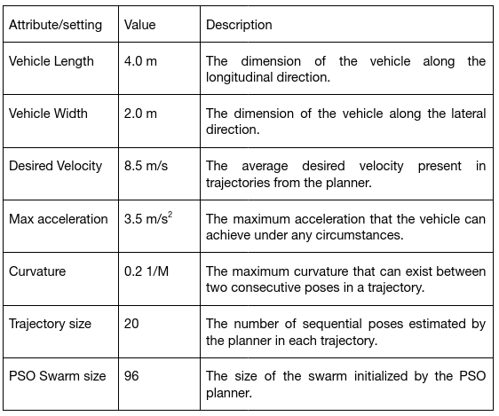
The parameters along with their definition that were adjusted for modelling automated driving vehicles for the present use case are the following:

3 Transferability
In this work, a modular driving pipeline that require sensor data (camera, lidar, etc.) was deployed and tested on a street level simulation in Carla simulator. In the following, we discuss the minimum set of requirements required to transfer or integrate the driving function into other simulators.
- Input requirements:
- Lanelet file: This file is required for the driving pipeline to infer the road geometry and topology such as the road boundaries, road curvature, etc. Additionally, the GPS coordinates of the lanelet map origin should be defined and passed to the planner.
- Parameters: The essential parameters for the pipeline operation are illustrated in the previous section and without the definition of these parameters such as the vehicle length, width, etc. Correct behaviour of driving cannot be guaranteed.
- A transformation between the map origin and the current vehicle poses. This transformation is crucial in localizing the vehicle in the lanelet map.
- A cost map to infer information about the occupancy of static obstacles as well as a list of dynamic obstacles in the environment. In the current work, the cost map and the obstacles list are derived from lidar sensors as discussed in section 1 – perception.
- Output requirements:
- The final output from the pipeline is an Ackermann command. To successfully integrate the pipeline with other simulators, an adapter that converts the Ackermann commands to actual vehicle motion in the simulation is required.
References
- P. Bender, J. Ziegler, and C. Stiller, “Lanelets: Efficient map representation for autonomous driving,” Intelligent Vehicles Symposium (IV), 2014.
- F. Poggenhans et al., “Lanelet2: A high-definition map framework for the future of automated driving,” in International Conference on Intelligent Transportation Systems (ITSC), 2018.
- M. Althoff, S. Urban, and M. Koschi, “Automatic conversion of road networks from opendrive to lanelets,” in International Conference on Service Operations and Logistics, and Informatics (SOLI), 2018.
- W. Hess et al., “Real-time loop closure in 2d lidar slam,” in IEEE International Conference on Robotics and Automation (ICRA), 2016.
- F. Hasecke, L. Hahn, and A. Kummert, “Flic: Fast lidar image clustering,” arXiv:2003.00575, 2020.
- X. Zhang et al., “Efficient l-shape fitting for vehicle detection using laser scanners,” in IEEE Intelligent Vehicles Symposium (IV), 2017.
- B.-N. Vo and W.-K. Ma, “The gaussian mixture probability hypothesis density filter,” IEEE Transactions on signal processing, vol. 54, 2006.